Rear Differential
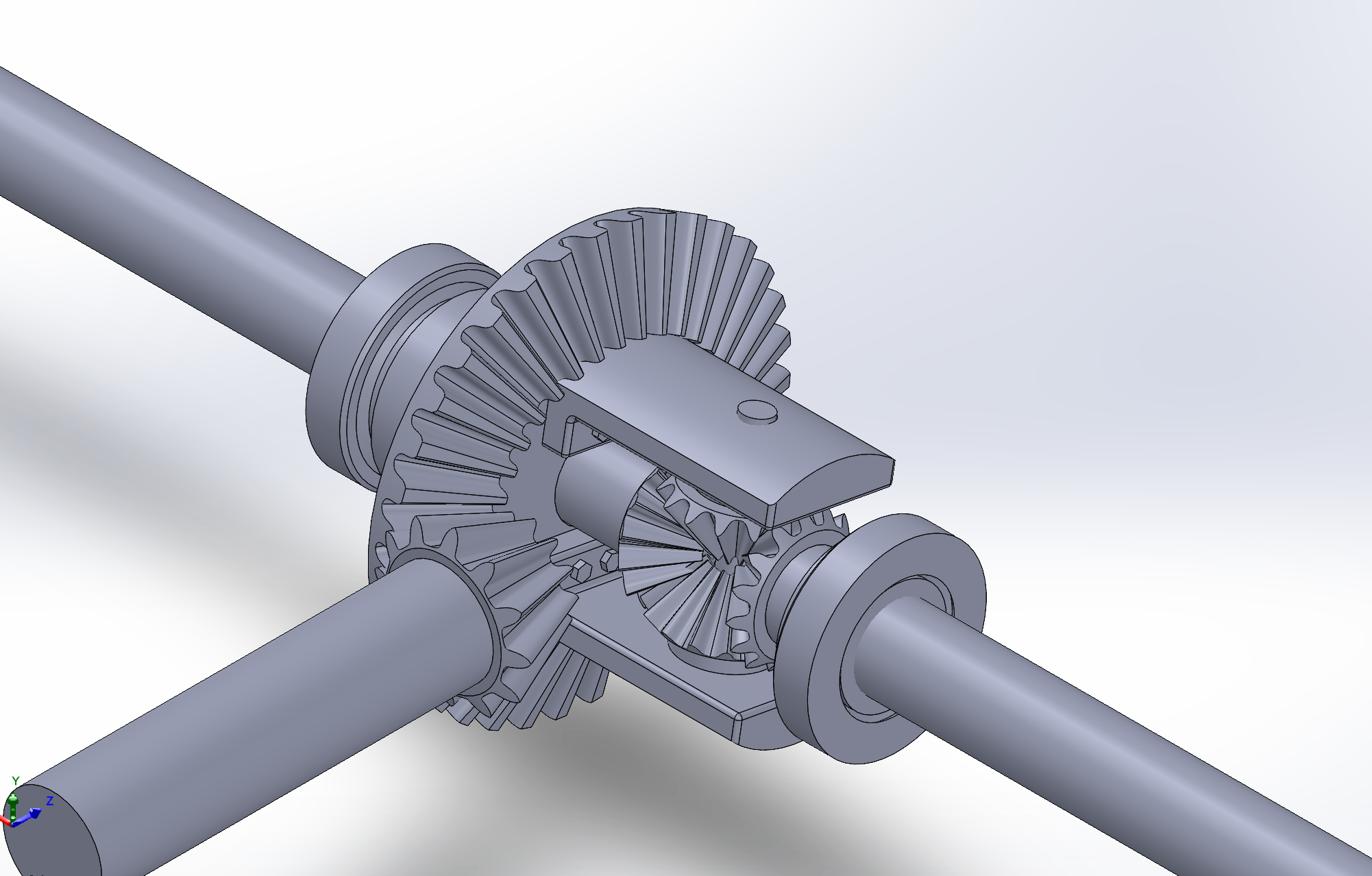
An industry-standard rear differential CAD model
About the Project
This project was my final grade for a CAD/Fabrication class, where we were tasked with reverse engineering any system we see around us daily using SOLIDWORKS. My choice was a rear differential from a car, as it would teach me about gear ratios and gear mating in SOLIDWORKS. I started by researching dimensions and part models of different rear differentials online. Using that info, I designed 7 individual part models, as well as used McMaster-Carr to implement screws and bolts.
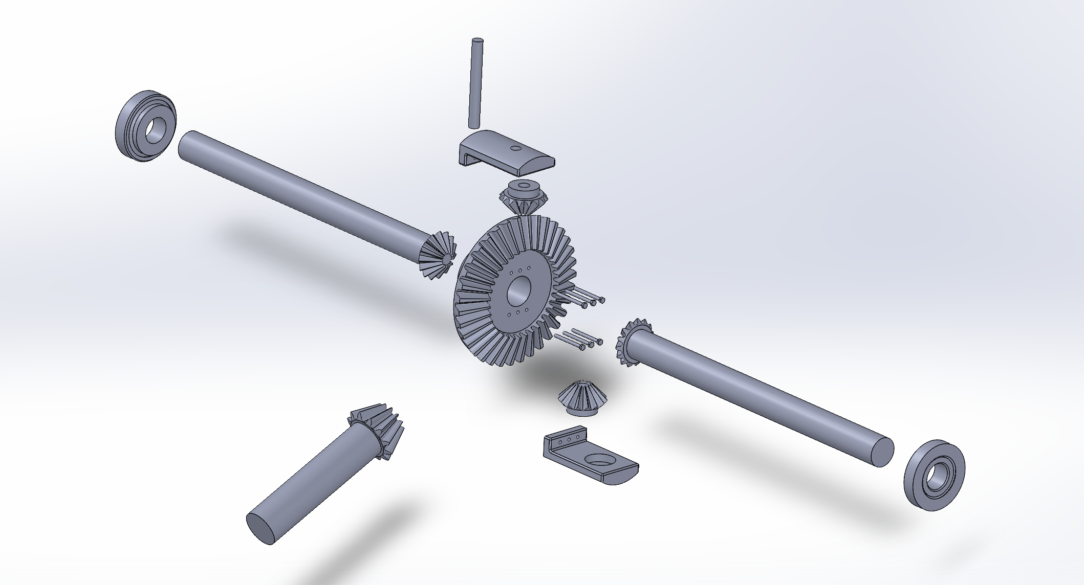
I then combined these part models into one fully mated assembly which could rotate on two axes to demonstrate the functionallity of the system. This assembly model came with both a mated view and an exploded view to better illustrate the indivudual parts.
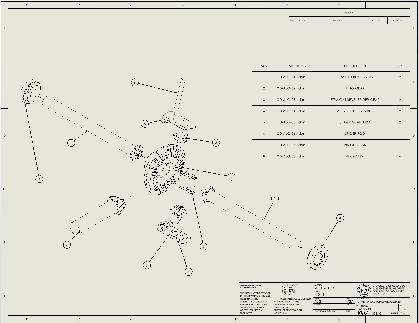
From there, I made engineering drawings of each part, complete with correct tolerences and GD&T application. My final step was to create a drawing of the entire assembly which included a Bill of Materials. Included below are images of the mated and exploded views of the assembly, as well as the drawing + BOM.